ARRAX
Design and test of a rocket engine
1000N (225 lbf) of thrust
10 bar (145 psi) of chamber pressure
LOX/ETH
Pintle injector
Regenerative cooling
Thrust vector control
1 kN de poussée
10 bars (145 psi) of chamber pressure
LOX/ETH
Pintle injector
Regenerative cooling
Thrust vector control
1 kN de poussée
10 bars (145 psi) of chamber pressure
LOX/ETH
Pintle injector
Regenerative cooling
Thrust vector control
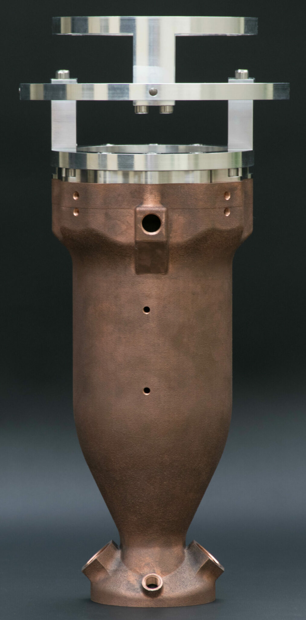
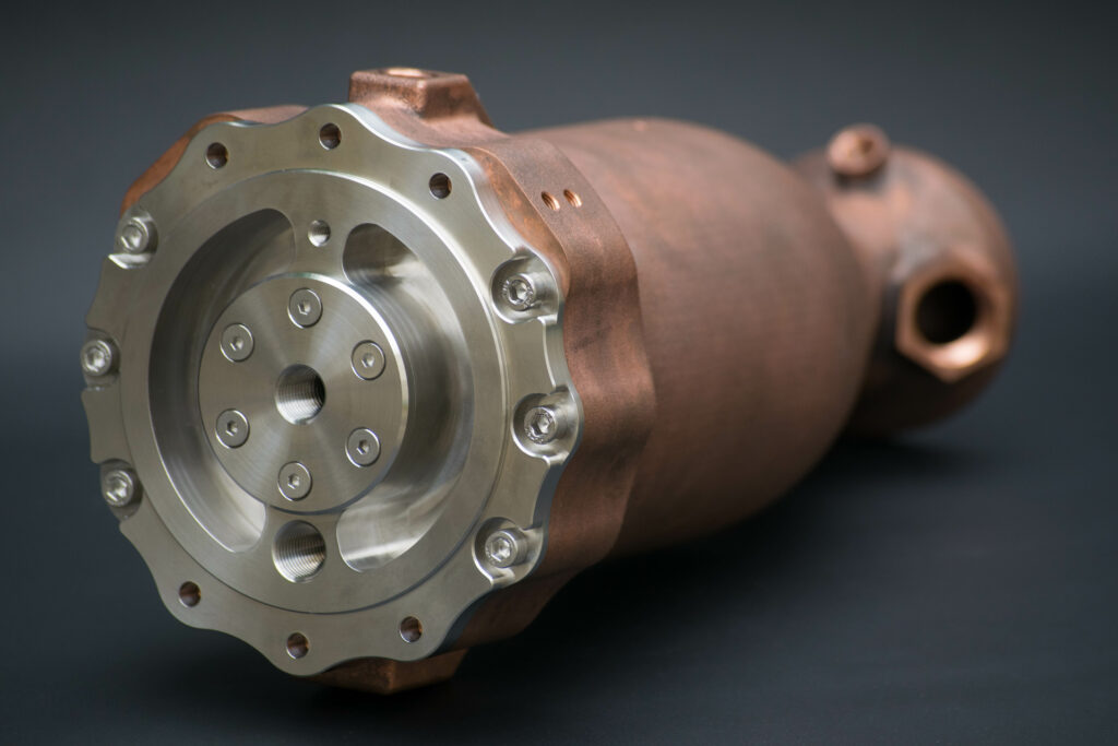
Pintle injection
The pintle injector is the heart of our liquid bipropellant rocket engine. It consists of an injector plate and a central component called the pintle. This system is designed to provide optimal propellant flow, atomization, and mixing. As the centerpiece of our engine, it plays a crucial role in determining combustion efficiency. The pintle is directly attached to the injector plate and is responsible for delivering a controlled amount of LOX into the combustion chamber. The injector plate, on the other hand, is inserted into the combustion chamber and injects a ring of ethanol that is impacted by the LOX radially exiting the pintle. This collision ensures the dispersion of fine droplets of propellants, which facilitates their evaporation.
Regenerative cooling
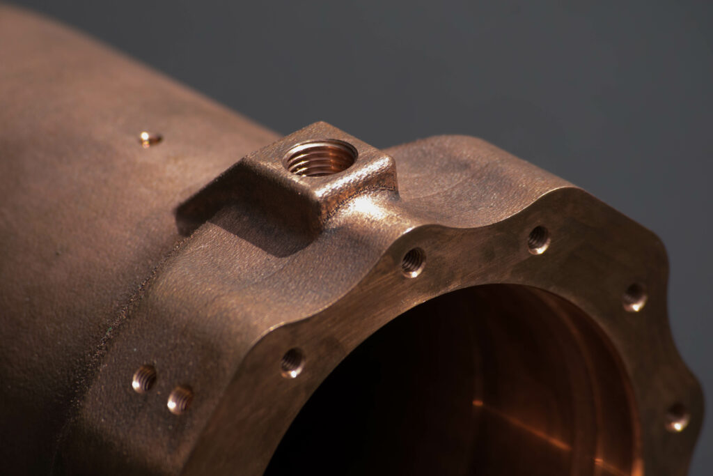
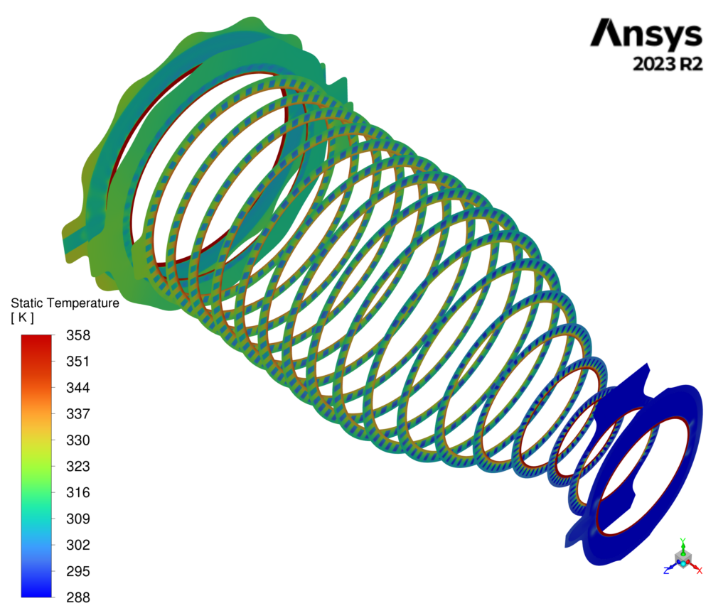
Regenerative cooling
Regenerative cooling is a rocket engine combustion chamber cooling technique. Its principle relies on circulating one of the propellants (usually the fuel) through cooling channels along the chamber. The channels and the chamber of the Arrax have been modeled using a Python program developed by us, which automatically generates the channel dimensions based on a few parameters. The cooling system also includes the design of a constant-speed distribution ring that ensures even fluid distribution so that the inlet velocity is uniform across all channels. Additionally, there is the design of a recovery ring aimed at collecting the coolant and directing it to the appropriate location (e.g., injector plate).
Thrust Vector Control
Thrust Vector Control (TVC) describes the ability to change the direction of a rocket engine's thrust. To achieve this, we use two actuators that hold the engine and control its orientation, along with a gimbal. The gimbal is a component that allows the engine to pivot up to 12° in any direction while supporting its thrust.

Ignition
The ignition of a rocket engine is a critical phase of the combustion process. Poor coordination between the ignition and the arrival of the propellants in the combustion chamber can lead to a hard start: an overpressure caused by the sudden combustion of a large amount of propellants. Ignition requires an initial flame or spark to initiate the combustion. To achieve this, we use a pyrotechnic cartridge igniter. The cartridge igniter is set alight upon contact with a heated wire, which is electrically powered, and it starts the combustion of the propellants in the chamber.
The design of our rocket engine is now complete. The combustion chamber was made using metal additive manufacturing (Metal AM) by MakerVerse™, while Protolabs™ machined the components for the injection system and the gimbal.
Our goal now is to test this engine. We have therefore undertaken the design of a test bench.
Test
Bench
To safely test the engine, we need to be able to store the propellants, manage their delivery to the combustion chamber, and remotely control the combustion. To achieve this, the design of the test bench is built around three main axes.
Structure and fluid systems
The test bench must support the weight of the tanks and the engine, as well as the force it exerts during combustion. To ensure the engine is properly supplied with propellants, it is essential that the tanks are correctly pressurized. To achieve this, we will use a gaseous nitrogen line, as it does not react with the propellants. This line will also serve as a purge for the ethanol and LOX lines. To simplify the engine design, we have chosen to cool it using a high flow rate of water pressurized with air.
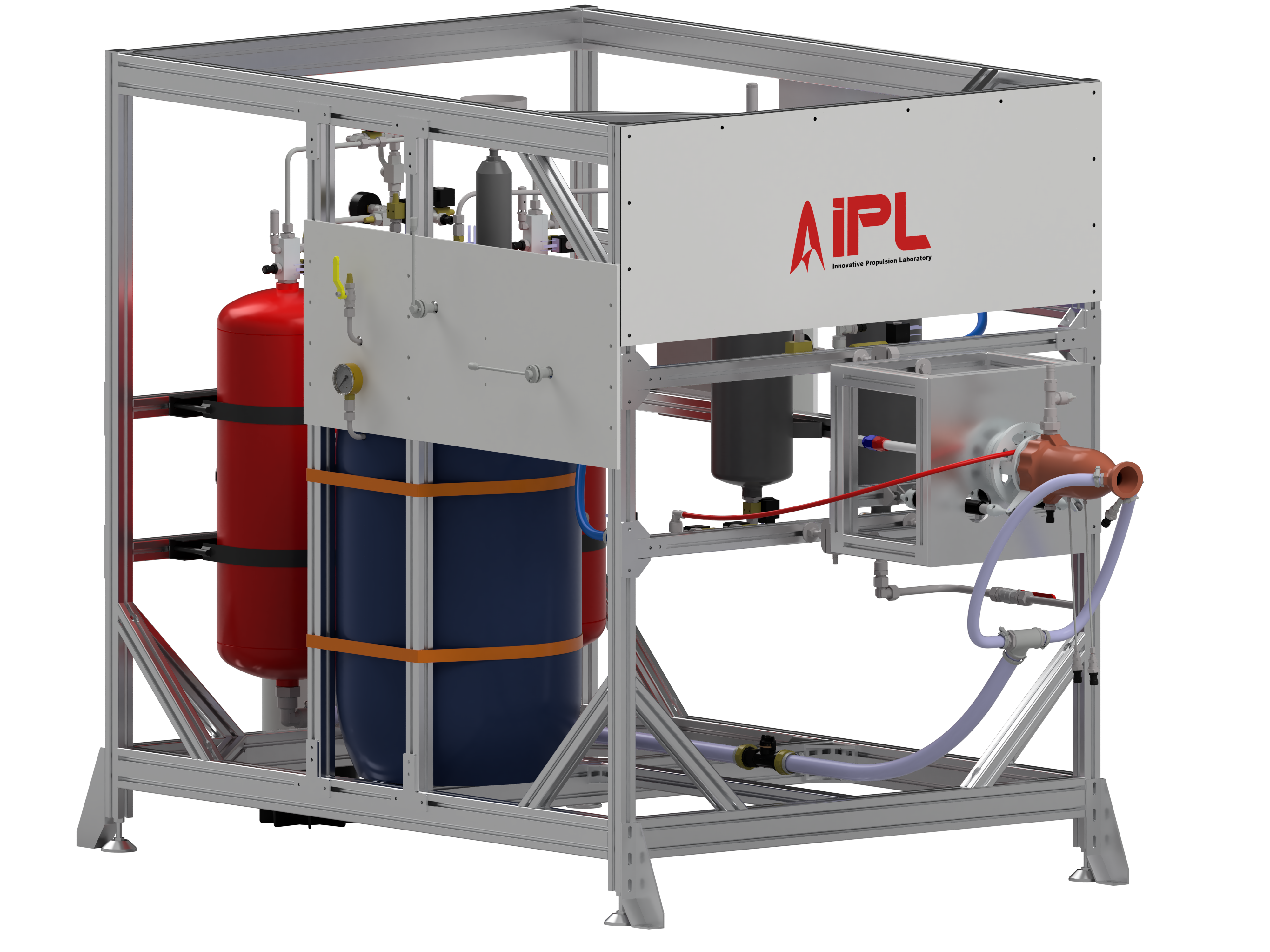
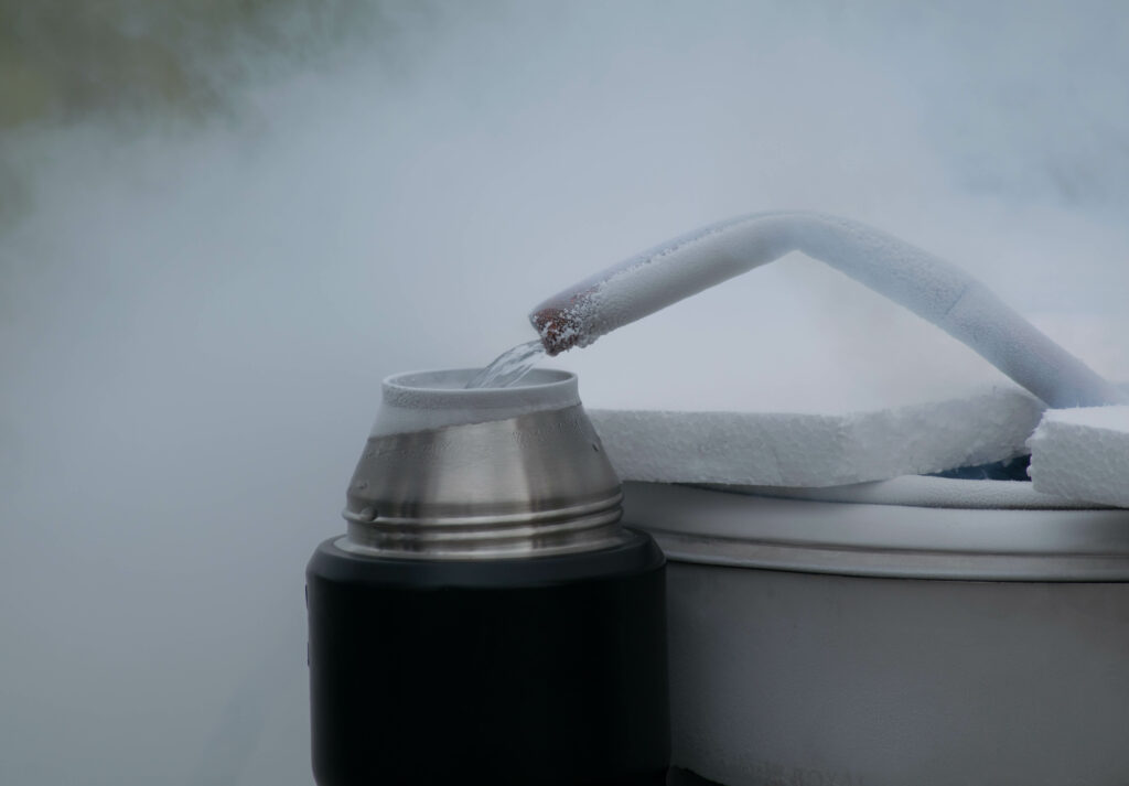
Liquid oxygen production
Our engine operates with liquid oxygen (LOX), which has a boiling point of -183°C (at 1 atm). To liquefy our oxidizer, we will use a copper coil as a heat exchanger immersed in liquid nitrogen at a temperature of -196°C. Once the LOX is obtained, it will be stored in a tank immersed in liquid nitrogen and surrounded by insulation to prevent evaporation.
Engine control and
data acquisition
For the hotfire tests to be conducted safely, we need to be able to remotely control the pressurization of the tanks and the combustion inside the chamber. Additionally, we want to program the actuators responsible for thrust vector control (TVC) and collect data from the pressure, temperature, flow rate, and force sensors placed at strategic locations on the test bench. To achieve this, we have chosen an architecture built around the Teensy 4.1 microcontroller, connected via Ethernet, which handles data collection and transmission. In parallel, we are developing a Human-Machine Interface (HMI) using Python. The HMI displays real-time values from each sensor, provides an overview of the test bench's status (including valve and actuator positions and sensor readings), and controls the actuators.